The Problem
If you were to carefully read the product specifications for the Class-T Audio Mini Amplifier and Marine Certified Speakers I'm using in my solar-powered stereo, you would notice that the Amplifier produces frequencies ranging from 20 hertz to 20 kilohertz (about the range of human hearing), but the speakers only can reproduce 60 Hz to 20 kHz. Feeding the speakers lower frequencies than they can handle is not ideal (and actually potentially damaging to the speaker), but there is a solution: a crossover filter.
What is a Crossover Filter?
DIY Audio & Video has a good Speaker Crossover Wiring FAQ that has this explanation of a crossover:
“What is a crossover?
People can hear sound frequencies from 20-20000Hz. There is no one speaker capable of producing all frequencies throughout this range. Therefore, multiple speakers must be used. Usually, it is damaging for a speaker to produce frequencies lower than what it was designed for. Also, if two speakers produce sound at the same frequencies, then the sound at those frequencies will be louder. For these reasons, some type of circuit is necessary to make sure that each speaker only produces a certain set of frequencies. That circuit is a crossover. ”
This image from their site illustrates the point:

Fortunately for my stereo project, the woofer and tweeter are part of the same package, so they have already been corrected for the overlap frequencies. But I still have the problem of the amp producing frequencies too low for the speakers to reproduce. This will lead to the speakers sounding distorted at moderate to loud volumes when reproducing lower frequencies. This same crossover filter can be used to remove all frequencies too low for the speaker to reproduce correctly.
What do I need to make a Crossover Filter?
“What makes a crossover?
The basic components of crossovers are inductors and capacitors. Inductors become more reactive (increasing AC resistance) as the frequency increases, and thus lower the sound pressure on the driver more and more as the frequency increase. Capacitors work just the opposite. They have higher AC resistance as the frequency decreases. Inductors, Capacitors, and Resistors are also used in other circuits like Notch Filters and Attenuation Circuits which can sometimes be included in the ‘crossover’. ”
For my purposes, the simplest type of crossover will do. That type is the 1st order Butterworth crossover. Here's an illustration (from DIY A&V):
As you can see, they placed a capacitor on the positive lead to the tweeter to filter out frequencies below 3000 Hz @ 8 Ohms (random values for this example), because capacitors have higher AC resistance as the frequency decreases, so this will filter out low frequency sounds that could be damaging for the tweeter. Conversely, they put an inductor on the woofer to eliminate higher frequency sounds. Here we are only interested in removing lower frequencies from our speaker, so we will only use a capacitor, and we will place it before the entire speaker system.
“What type of capacitor should I buy?
For capacitors, a polar Electrolytic capacitor is your basic type. They are cheap, but do not pass high frequencies well. Mylar capacitors are more expensive, but they are better for audio because they work better at the high frequencies, and have less inductance and resistance. Metalized Polypropylene capacitors are the best, but are also much more expensive. Again, be sure to investigate the resistance of these components before purchasing.”
For my purposes, I just bought Aluminum Electrolytic Capacitors, but I opted for the Non-polar/Bi-polar variety because they are better for audio purposes.
The next question is, what value capacitor should I buy? A crossover filter has 3 variables:
- the impedance of the speaker (Ohms)
- the frequency (hertz) below which you want to filter, and
- the capacitance of the resistor.
We know from the specifications that our speakers are 4 Ohms, and we want to filter at 60 Hz because the speaker's rated Frequency Response is 60 Hz to 20 kHz. With these two variables, we can calculate the 3rd. DIY A&V has a Crossover Calculator for this purpose. The results for my specifications are as follows:

Again, ignore the inductor portion, we are only concerned with the value for the capacitor, which is calculated to be 662.5 microfarad. From here I went to Mouser to search for this value capacitor. Now maybe you can guess this, but 662.5 uF is not a standard value for capacitors that are normally manufactured. So I needed to look for something close to that value.
I could either round up or round down, and if you do the math (or use the calculator to check), you'll see that lower capacitance means the cutoff frequency increases, so I would start losing frequencies above 60 Hz that my speaker is perfectly capable of reproducing. Conversely, if the capacitance value increases, the cutoff frequency decreases, and if you go to far down in capacitance we're no longer solving the problem of removing frequencies the speaker cannot accurately reproduce. So you have to be careful going in either direction. Also, be aware that manufacturing tolerances on the speaker, amp, capacitors, etc are not very tight, so it's not possible to be too accurate until you actually buy the parts and measure the values yourself. But I'll discuss manufacturing tolerances more later.
The closest value for a widely manufactured capacitor I could find was 680 uF. Though unfortunately there did not seem to be any non-polar/bi-polar capacitors at that capacitance.
Wiring in Parallel or in Series
“I can’t find a inductor/capacitor/resistor of the value I need. What should I do?
When you buy inductors capacitors or resistors there are usually only certain values available. ... If you cannot find the component you need, then go with the closest match. You can also combine two components in Parallel or Series to get a different value that you can’t find normally. ”
The Basic Electronics page at DIY A&V explains how you can wire capacitors in parallel or series to obtain a higher or lower value for overall capacitance. Here's a few illustrations from that website:
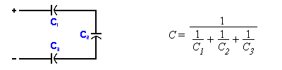

On the left is the diagram and formula for wiring in series, and on the right is the same for wiring in parallel. If you do the math, you'll find that the overall capacitance is reduced if you wire multiple capacitors in series, and increased if you wire multiple capacitors in parallel. With our target value of about 660 uF as a starting point, capacitors generally get more expensive as the capacitance increases, and cheaper (and more common) as the capacitance decreases (at least until you get to very low values, then price and rarity might go up again). So for our purposes, we want to wire in parallel to be able to use more commonly found resistors. 660 uF is not a very common capacitance value, but 330 uF is, so I used two 330 uF capacitors wired in parallel for a total capacitance of 660 uF. The particular capacitors I bought are from mouser at this link:
Nichicon Aluminum Electrolytic Capacitors - Leaded 50volts 330uF 85c 16x31.5 7.5LS
I ordered capacitors with 50 volt rating because you want to have a lot of headroom over the actual power that will be going through the circuit so the capacitors don't blow out. 50 is a good minimum, it's fine to go higher, but the capacitors will increase in physical size (they are already pretty big at 50).
Manufacturing Tolerances
Here's where things get interesting.
If you look at the specifications for the capacitors I linked to above, you'll see that they have a tolerance rating of 20%. This means that even though it's listed as a 330 uF capacitor, what you actually get might have a capacitance of +/- 20% of that value, so from 264 - 396 uF. As you can imagine, this has a pretty large impact on our calculations.
It's not just capacitors that have wide tolerances, the speakers, amplifier, resistors, all of them are manufactured to specs to some degree of accuracy. If you pay a lot of money, you can buy components with very narrow tolerances. But the cheaper option for manufacturers is to have wide tolerances, and rate their products accordingly. For good manufacturers, this usually means they will err on the side of giving you a better product than the rating.
So I ordered 10 of these capacitors (I only need 4, but bulk pricing kicks in at 10 for Mouser, and it's helpful to have spares), and then measured them when they arrived with a multimeter that can measure capacitance. Then I did some calculations to figure out what the actual cutoff frequencies would be (I used this other crossover calculator this time, because it lets you plug in capacitor values and get the responding corner/cutoff frequency, and not just the other way around). Here are the results:
The first thing to notice here is that the measured capacitance of the capacitors is about 8-12% greater than the rated values. Capacitor manufacturers usually err on the side of increased capacitance, because more capacitance is not a problem in the most common circuits.
Calculating out the cutoff frequencies results in 53.7 Hz to 55.7 Hz for 4 Ohm speakers, which is what the speakers I bought are rated. But, if you were to measure the resistance of these speakers, it is actually 4.4 Ohms, so that means the cutoff frequencies will be closer to the range of 48.8 Hz to 50.6 Hz. This is a little lower than the 60 Hz minimum frequency response the speakers are rated for, but hopefully the actual response of the speaker is a little better than the rating. And filtering out the really low frequencies is the most important thing anyway, as they are the most distorting or potentially damaging.
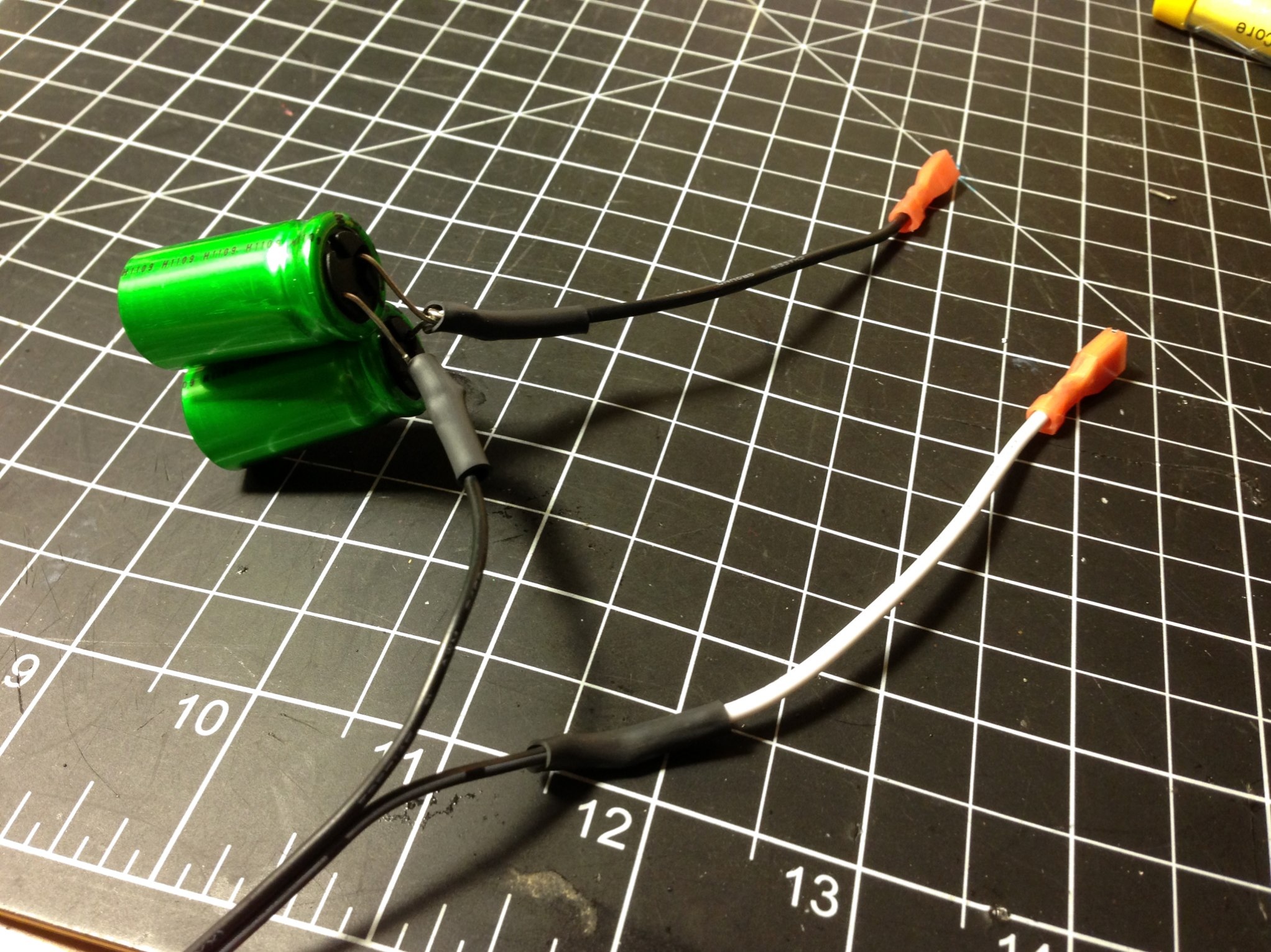
So now I just had to wire these capacitors in parallel. Being an amateur myself at soldering and circuitry, this is what I came up with at first:

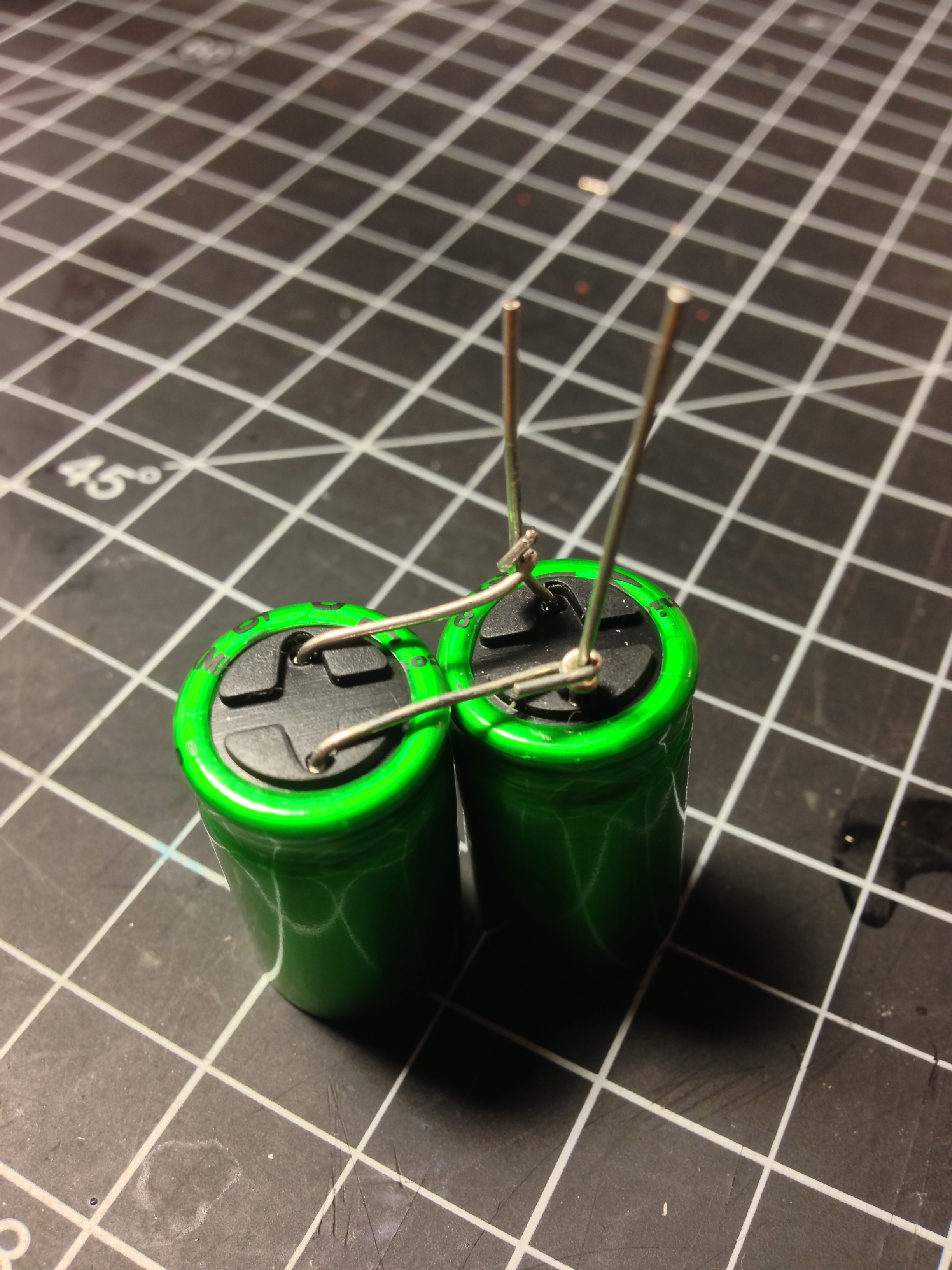
My roommate (who is much better with electronics because he makes and sells his own guitar pedals) saw this and suggested a much simpler design by wrapping the two capacitor's leads together and soldering them to a wire as if they were one:
After installing these, the speakers distort a lot less when compared to the same volume & EQ setting being played through a simple speaker wire with no crossover filter.
Now the focus will shift to building the casing. One small aspect of that will be securing these capacitors to something (whether it be through glue or zip-ties, etc) so they don't move around and potentially short something out with their exposed metal.
Previous posts about the Solar-Powered Stereo project:
Power indicator LED, voltage gauge
Solar-Powered Stereo (test build)